31 Results
View results:
Sort by:
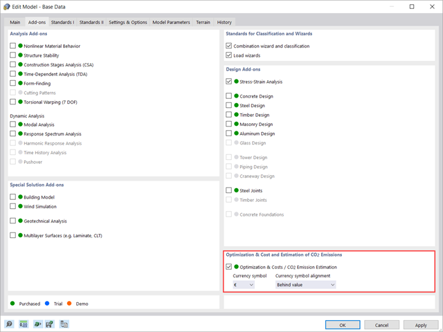
This article shows you how to use the add-on Optimization & Costs / CO2 Emission Estimation to estimate the model costs. Furthermore, it shows you how to optimize parameters based on minimum cost when working with parameterized models and blocks.

This article describes how a flat slab of a residential building is modeled in RFEM 6 and designed according to Eurocode 2. The plate is 24 cm thick and is supported by 45/45/300 cm columns at distances of 6.75 m in both the X and Y directions (Image 1). The columns are modeled as elastic nodal supports by determining the spring stiffness based on the boundary conditions (Image 2). C35/45 concrete and B 500 S (A) reinforcing steel are selected as the materials for the design.
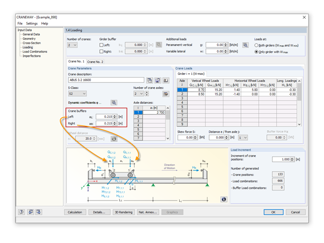
In the event of converting or extending a hall, the building owner may want to add a second or third crane to an existing crane runway. Since the original design usually does not consider other cranes, a common solution is to design a minimum distance between the cranes. This is done via the crane technology settings.

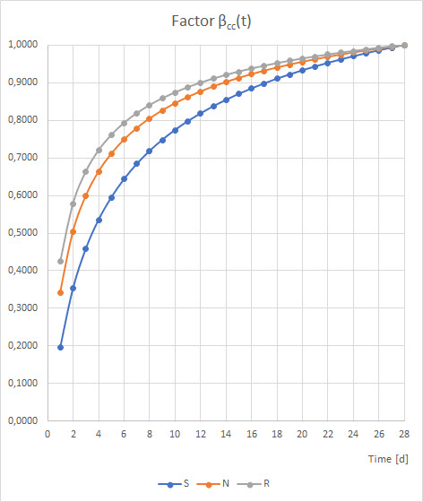
In the case of using slow‑curing concrete (usually for thick components), you can reduce the calculated minimum reinforcement by a factor of 0.85 to apply the load due to restraint, according to EN 1992‑1‑1, Section 7.3.2. However, a precondition for reduction is that the characteristic value of the strength development r = fcm2 / fcm28 does not exceed 0.3. Other key requirements for the application of this reinforcement reduction are specified explicitly in the final planning documents.

With the RF-/TIMBER Pro add-on module, you can perform the vibration design known from DIN 1052 for the design according to EN 1995-1-1. In this design, the deflection under permanent and quasi-permanent action at the ideal one‑span beam may not exceed the limit value (6 mm according to DIN 1052). If you consider the relation between the natural frequency and the deflection for a hinged single-span beam subjected to a constant distributed load, the 6 mm limit value results in a minimum natural frequency of about 7.2 Hz.

For uniformly distributed loading according to EN 1992‑1‑1 (Eurocode 2), the design section for the shear reinforcement can be placed at the distance d from the front edge of the support. Thus for the shear reinforcement, the applied shear force is reduced to VEd,red. To analyze the maximum design shear resistance VRd,max, however, the total shear force is applied.

In RF‑/CONCRETE Columns, different methods are available for defining the minimum longitudinal reinforcement. The minimum reinforcement can be selected according to the design standard used and/or specified by the user.
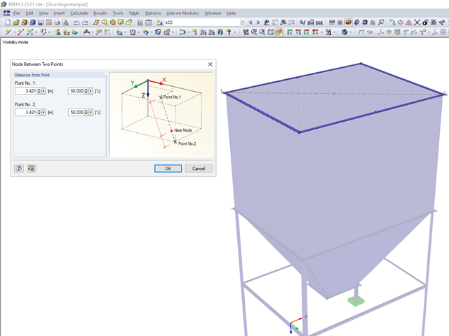
Until now, if you wanted to determine the centroid of a rectangle, it was necessary to define a line from one corner point to the diagonally opposite point. You obtained the centroid by dividing this line. In RFEM 5 and RSTAB 8, you now have the possibility to create a node between two points. Thus, it is sufficient to select the corner points; then you can determine the distance in absolute or relative values.

For cross‑laminated structures with large spans, downstand beams or hybrid structures are often used. They can be modeled in RFEM 5 by using surfaces and member cross‑sections. In both structural systems, curved downstand beams are also possible without any problems. In the case of the curved surface, the member is always appropriately generated by means of the automatic member eccentricity with the thickness distance of the surface and the member. The downstand beam can also be connected flexibly by means of a line release.
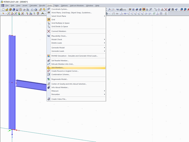
To join free members to the members located within a certain maximum distance, use the "Join members" function.

The RX‑TIMBER stand-alone program offers you the option to optimize the lateral-torsional bracing. With this selection, the program iteratively determines the required minimum length of the lateral-torsional bracing.
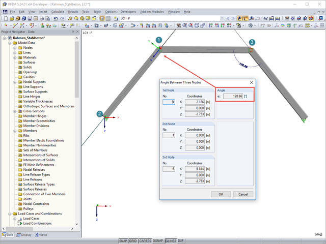
To determine the distance between two nodes or the angle between two objects without using the dimensioning function, you can simply use the "Measure" option on the "Tools" menu. Here, you can also choose between various measure functions.
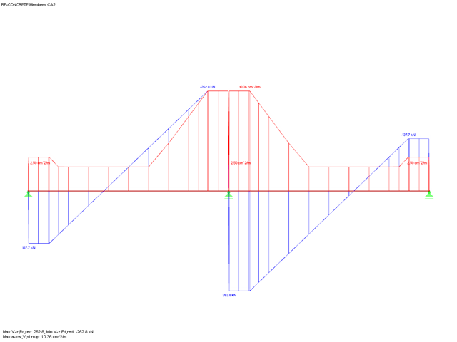
When performing shear force design in RF-CONCRETE Members and CONCRETE, you can reduce the acting shear force Vz according to EN 1992-1-1. The following article describes the reduction of the concentrated loads close to the support and the shear force design at the distance d from the support face for a uniform load.

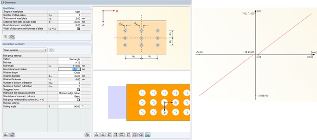
This technical article deals with the stability analysis of a roof purlin, which is connected without stiffeners by means of a bolt connection on the lower flange to have a minimum manufacturing effort.
When determining the minimum reinforcement for the serviceability limit state according to 7.3.2, the applied effective tensile strength fct,eff has a significant influence on the determined amount of reinforcement. The following article gives an overview about determining the effective tensile strength fct,eff and the input options in RF-CONCRETE.

When modeling a reinforced concrete rib with a masonry wall above, there is the risk that the rib is underdesigned if the structural behavior of the masonry is not correctly considered and the connection between the masonry wall and downstand beam is not modeled sufficiently accurately. This article deals with this issue and shows the possible modeling options of such a structure. In this example, the reinforcement is determined only from the internal forces and without secondary minimum reinforcement.
From time to time, two intersecting beams overlap at a short distance. Such a structure raises the question, with regard to the modeling, of how it is possible to consider a contact with force transmission under compression between the two beams, while the contact under tension (for example, in case of a lifting top beam) should fail.

The secondary reinforcement according to DIN EN 1992-1-1 9.2.1 is used to ensure the desired structural behavior. It should avoid failure without prior notification. The minimum reinforcement has to be arranged independently of the size of the actual loading.

According to Clause 7.3.2 (2), standard DIN EN 1992-1-1 requires: "In profiled cross‑sections like T‑beams and box girders, the minimum reinforcement should be determined for the individual parts of the section (webs, flanges)." In the case of a floor beam with a T‑section, the minimum reinforcement should be determined for both flanges and the web if the corresponding partial cross‑sections are in the tension area. Image 01 shows the division into partial cross-sections.
![Residual Stresses, Zero Line Position, and Tearing Depth when Cooling Pane on both Sides [2]](/en/webimage/009621/2419687/01-en-png-png.png?mw=640&hash=5e657e3feb5c1bb6d21727468dd85d91e1c9f29f)
Generally, avoiding cracking in concrete structures is neither possible nor necessary. However, cracking must be limited in a way so that the proper use, appearance, and durability of the structure are not affected. Therefore, limiting the crack width does not mean preventing from the crack formation, but restricting the crack width to harmless values.
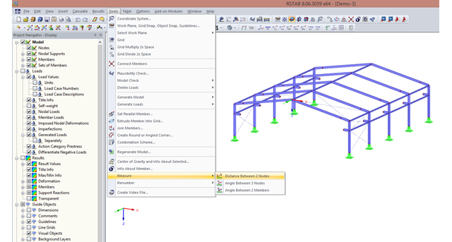
The "Measure" function available in the "Tools" menu allows you to measure distances and angles.
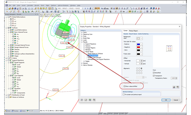
In the case of very small distances between isolines, the labels often overlap, which makes the result documentation difficult. As of RFEM version 5.06, you can select a shifted arrangement of the isoline labels in the Display Properties dialog box. By selecting the "Show values shifted" option, you can easily avoid overlapping the result values in many cases.
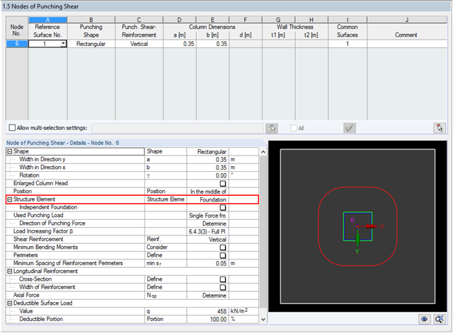
The RF‑PUNCH Pro add‑on module allows you to perform the punching shear design of floor slabs and foundation plates according to EN 1992‑1‑1. In the case of a floor slab, the basic control perimeter is applied according to 6.4.2 (1), EN 1992‑1‑1 [1] at a distance of 2d from the loaded area.
In RF-JOINTS Timber – Steel to Timber, you can consider the possible minimum slippage of bolts in the case of guide pins. In RFEM, this slippage is taken into account using the flexibility in member end releases.
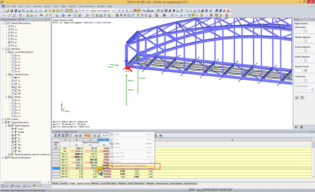
A result combination (RC) combines results from the selected load cases (LC), load combinations (CO), and result combinations according to a preset combination syntax. Since a particular result may show an extreme value, depending on the combination at various locations of the structure, the RC displays the maximum and the minimum values for each result type.
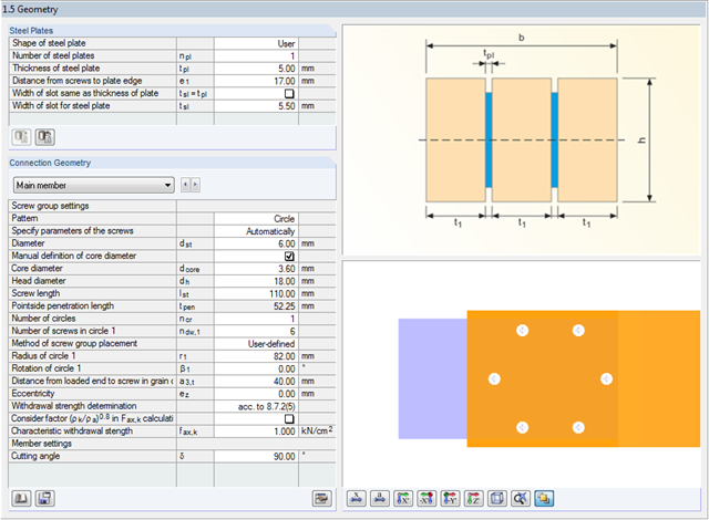
In RF-/JOINTS Timber – Steel to Timber, you can select a circular connection type for the dowel, bolt, nail, and screw joint categories. For this connection type, the minimum radius is set in compliance with the recommendations of the STEP-1 report of the German Information Service Timber.
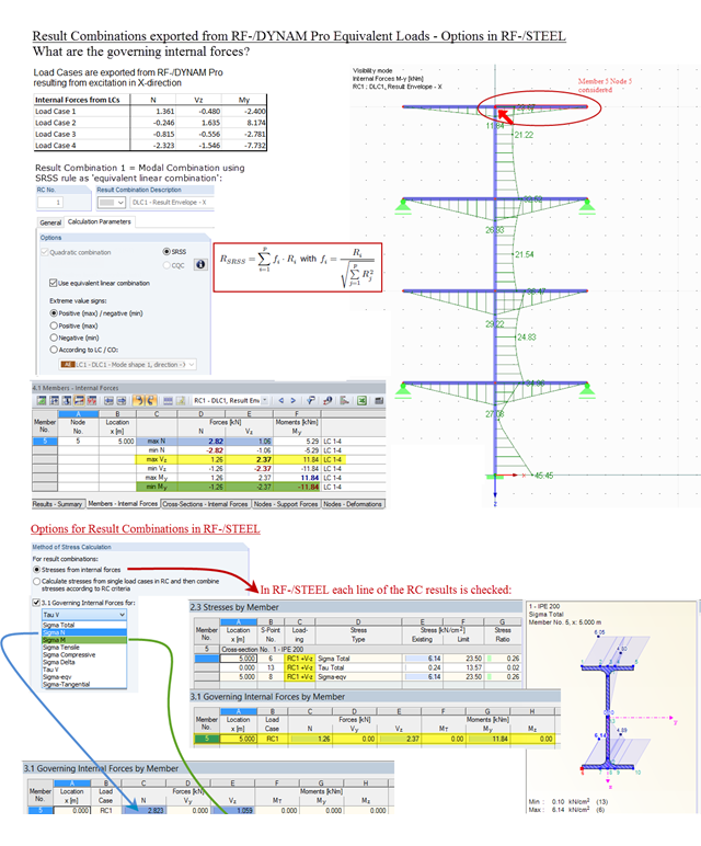
Result combinations exported from RF‑/DYNAM Pro – Equivalent Loads are generated by superimposing the results from the individual modal responses. For this, the SRSS rule can be used as "equivalent linear combination". When result combinations are used in RF‑/STEEL, two options are available for calculating stresses. In the first option, the results from the result combinations are used directly. This is done line by line, for each maximum and minimum controlling internal force. In the second option, stresses are determined from the individual load cases. The quadratic superposition rule is then performed again in RF-/STEEL.
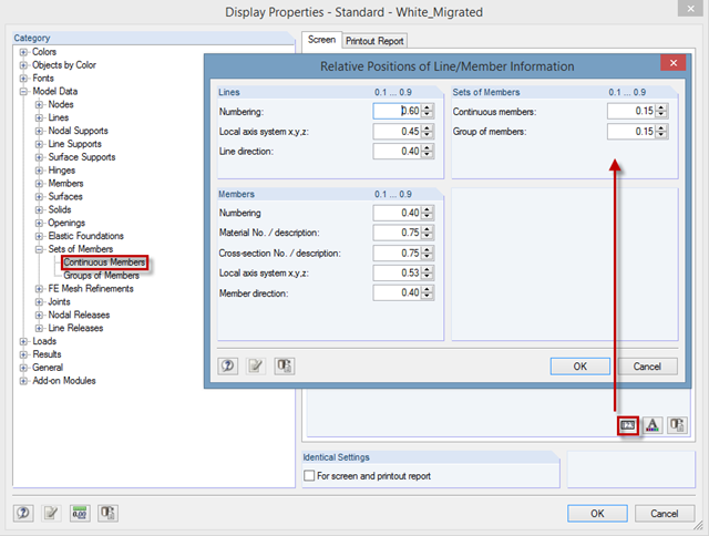
In RFEM and RSTAB, you can arrange the labeling of lines, members, and sets of members in a user‑defined way. To do this, open the dialog box in "Display Properties", where you can define the position of the information about the relative distance from the member start.
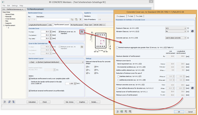
RF-/CONCRETE automatically determines the minimum concrete cover according to the standard. The calculation is based on the exposure class, the abrasion class, and the concrete cast.
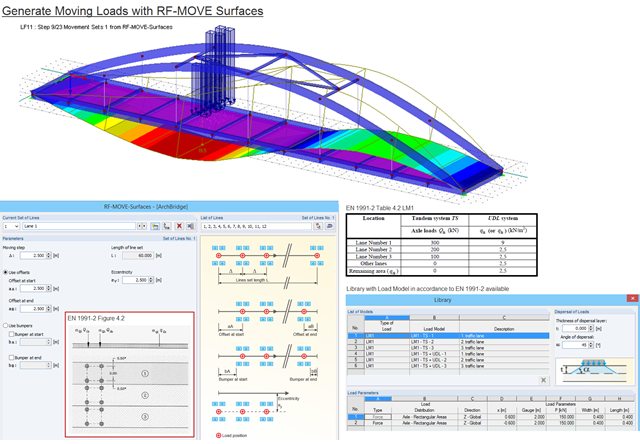
Moving loads can be generated easily with RF‑MOVE Surfaces. A library is available with load models as defined in Eurocode 1, Part 2. The input of step size, offsets at start and end, and the distance to a reference line make it possible for the user to generate user‑defined load models and influence the number of load cases generated. RF‑MOVE Surfaces generates load cases and, optionally, a result combination as an envelope of all results.